Development of Plasma Ignition Systems in Microwaves
Description
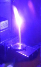
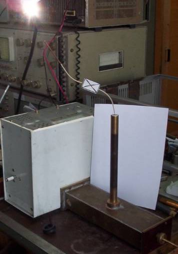
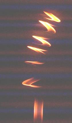
The set-up based on microwave method of plasma ignition allows one to ignite the plasma combus-tion processing directly at the needed point. This can be done due to a high density of microwave energy in small area at the end of single-conductor line. The set-up allows one to turn the required energetic regime using microwave power control scheme. Application of single-conductor line provides effective and easy way to conduct the microwave power without losses to the re-quired region.
Innovative aspect and main advantages:
This technology is very attractive in plasma com-bustion systems application due to its low cost, simple design and since its easy in service such as conventional microwave oven. The set-up based on this technology can be operated in a wide fre-quency range from several GHz to THz and in a wide output power range from several W to hun-dreds kW with efficiency not less then 50 per-cents. Due to this flexibility of output power mode the proposed technology can be applied in wide class of plasma systems from the systems with small volume of plasma to rather big plasma systems. Another advantage of the proposed set-up is its compact dimensions, which is limited by only microwave oscillator size. The presented set-up consists of oscillator with power supply unit based on conventional microwave oven unit (400mm*400mm*200mm), waveguide resonator with length 250mm and single-conductor line (line length can be from several cm to several me-ters).
Areas of Application
The set-up based on this technology can be util-ized as plasma ignition system in plasma combus-tion technologies:
1) Plasma Assisted Combustion,
2) Metal Heat Treatment Industry,
3) Systems for Treatment of Soil and other Materials,
Plasma Aerodynamics.
Stage of Development:
The technology is tested, available for demonstra-tion – field tested. In particular, the set-up operat-ing in 2,45 GHz range for energy range up to 0,5 kW is tested in wide pressure range as plasma igniter system.
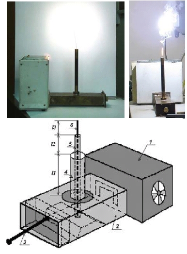

1) oscillator,
2) waveguide resonator,
3) plunger,
4) coaxial line,
5) inner conductor,
6) single – conductor line.
Experimental Methods for investigation Surface Wave Parameters
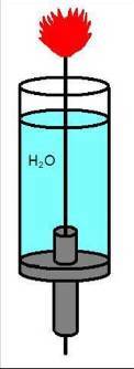
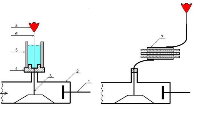
1) Plunger, 2) Coaxial-to-rectangular wave adapter, 3) Central conductor, 4) Dielectric bottom,
5) Dielectric cylindrical vessel, 6) Single-conductor line, 7) Periodical Layered Structure,
8) Flare Discharge.
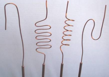
These forms of single-conductor line were used to show the surface character of energy transportation since, as it is shown in classical electrodynamics, such inhomogeneity application leads to a wave radiation from nonlinear region


